If you want to know What is cam, I invite you to read this article. Here you will find everything you need to know about this interesting computerized application that improves quality and reduces the costs of manufacturing processes in general.
What is cam?
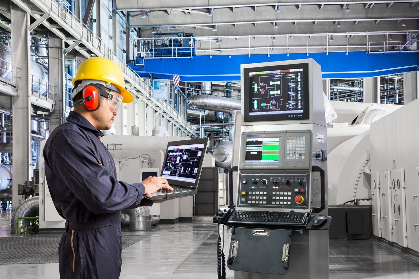
The term CAM, by the acronym in English that denotes simulation, modeling and product manufacturing applications (Computer Aided Manufacturing), is a type of technology that tries to automate separately a part of the production cycle, specifically planning, management and control of manufacturing operations. For this it makes use of computer systems, which contain an interface that allows communication with production resources.
In this regard, it is necessary to mention the existence of two types of interface related to CAM, these are:
- Direct interface: the computer connects directly with the production process, in order to supervise and control its resources and operations.
- Indirect interface: The computer is an aid tool in the manufacturing process, but there is no direct connection with it.
In this way, it can be said that the main task of CAM is to provide information and instructions that allow the automation of specialized machines in the manufacture of solid parts and pieces. For this, it requires the geometric documentation produced by Computer Aided Design (CAD).
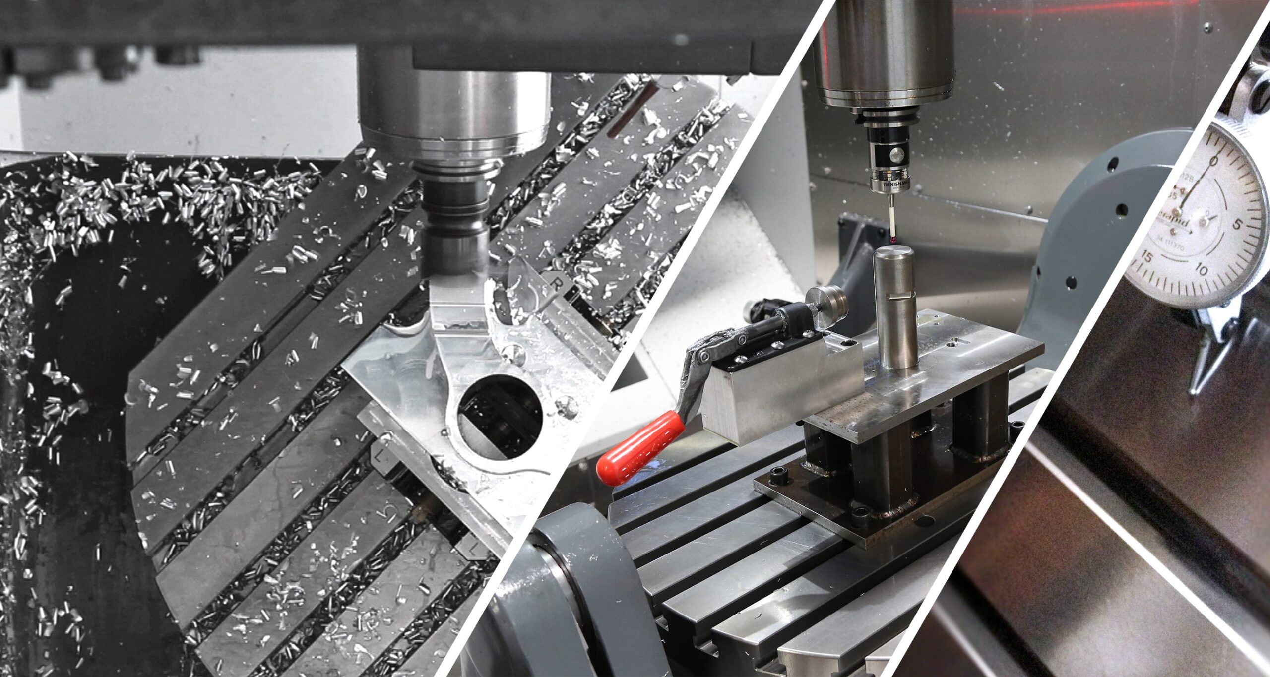
Another function of CAM is the programming of robots that select and position tools for computerized numerical control (CNC) machines. In addition to being able to perform other tasks, such as: painting, welding, and moving parts and equipment within moderate spaces.
On the other hand, before taking a tour of the evolution of CAM techniques, it is important to mention that the first attempt to develop this type of application was the programming of parts by numerical control. In other words, the generation of programs for numerically controlled machines capable of translating instructions into movements, including then the programming of robots and the concept of programmable logic controllers that exists today.
To better understand what What is cam, and its relationship with programmable logic controllers, you can read the following article: programmable logic controller. There you will find from the definition to its advantages and disadvantages.
History
The development of product design and manufacturing techniques is mainly due to the evolution of computers during the 50s. At that time, the first graphic screen emerged that allowed simple non-interactive drawings to be made. Similarly, the concept of numerical control programming was developed.
Later, with the advent of the stylus, the era of interactive graphics and design began.
A decade later, the CAD concept was introduced, along with some specialized systems in it, which coincided with the commercial launch of computer displays.
Ten years later, in the mid-70s, the industry exploited the potential of computer-aided design and manufacturing techniques, promoting the development of modeling systems and numerical control, among other important tools of this type. .
In the next ten years the use of CAD / CAM applications became widespread, along with advances in hardware and the emergence of three-dimensional tools. It was also the time when the concept of virtual reality emerged.
Later, in the 90s, the automation of industrial processes became widespread with the integration of digital techniques for design, analysis, simulation, and product manufacturing.
From there to the present time, the automation of industrial processes through computer-aided design and manufacturing has continued to increase, becoming the most viable and recommended option for the development of companies that seek to improve their production processes and reduce your manufacturing costs.
In our article automated processes You will learn more details about this interesting topic. Do not miss out!
Features
To know a little more about what What is cam, below we will mention its main characteristics:
- It involves the use of computers to assist in the product manufacturing process.
- Provides the tools to complement the geometry required to manufacture the part.
- Generate the code for the computer numerical control machine.
- Complements CAD technology for assisted manufacturing.
- It is made up of both the hardware and the manufacturing software, and the mechanisms that allow communication with the equipment.
Steps
In general terms, the manufacturing process of a product assisted by CAM technology involves the following stages:
- Process planning: Includes production planning, cost analysis, and the acquisition of tools and raw materials.
- Machining of parts: It involves the programming of numerical control.
- Inspection: Refers to the performance of quality control tests.
- Assembly: Requires robot simulation and programming.

After completing all these stages, the piece or final product is ready for packaging, marketing and distribution.
Advantages
Based on the definition, characteristics and stages of CAM, its advantages can be summarized as follows:
In general terms, it reduces the costs associated with labor and increases the capacity of the process, improving the quality of both the final product and its components. In other words, it simplifies, optimizes and raises the quality of the manufacturing process.
On the other hand, it facilitates the proposal of alternatives for the improvement of the tasks associated with the production process and minimizes the probability of errors by the human operator. In addition, it optimizes the distribution of the use of the machines, reducing the time that is invested in the development of the manufacturing process.
Similarly, it contributes to the creation and optimization of numerical control programs, eliminating the need for machine tests. In addition, it guarantees the proper use of the data and resources involved in the production process, increasing consistency and precision in the manufacture of mechanical parts.
Finally, it encourages and promotes the development of new technology.
However, as it is technology separate from the other parts of the production cycle, it is not possible to obtain all the comprehensive benefits of the product design and manufacturing process, making this its main disadvantage.
Fields of application
Due to its multiple functionalities, CAM techniques are increasingly used in sectors such as: mechanical, civil, electrical and electronic engineering, architecture, cartography, scientific, automotive and aerospace. With a tendency to increase its use, CAM has undoubtedly become the technology of the future.

Classification
Depending on the function they perform, there are several types of CAM systems. These are:
Systems for the coding of instructions
It requires the graphic identification by the user of the trajectories to be obtained on a CAD model. The numerical control code is generated automatically by the program.
Systems for the automatic generation of toolpaths
The user must establish which will be the surfaces to be machined, as well as the tools to be used. The system generates the trajectories and the code for the numerical control.
Simulation systems of a mechanized process
The toolpaths are generated either manually or automatically. The results obtained can be seen by drawing the trajectories followed or through the representation of the part after machining.
Systems to detect collisions
They are able to identify two types of interference. The first between the tool in its support and the piece to be machined, and the second between the table, the fixtures and the other elements of the environment.
Commercial software
There are various software alternatives on the market specialized in CAM techniques, each of which offers improvements over its predecessors. The main programs include the following:
- NC Vision: Based on our own CAD program, it allows us to choose the machining method of our preference. The trajectories are generated based on the previously specified cutting parameters.
- Catia: Despite being specialized CAD software, it has useful CAM tools. Its main characteristic is the generation of complete trajectories.
- NC Programmer: Based on the popular AUTOCAD program, the user must mark the start and end of the toolpaths on the CAD drawing.
- I-DEAS: Like the Catia software, it is a CAD program with CAM utilities. It allows to generate complete trajectories and identify collisions.
- Pro-Engineer: It has the same characteristics of the I-DEAS software.
- PowerMill: Software specialized in CAM manufacturing, basically aimed at the aerospace and automotive industry. It is capable of manufacturing highly complex shapes.
- RhinoCAM: CAM program capable of machining complex surfaces and solids with lathe, milling and drilling operations.
- SICUBE: Specialized in performing CAM laser cuts by generating automatic trajectories for 3D machines.
- SMIRT: Aimed at planning designs and dies, specifically used in automotive stamping.

CAD / CAM
It is a computer-aided design and manufacturing technology, whose main objective is to support the design, manufacture and development of products, improving precision and reducing manufacturing time and cost. This is achieved by combining two important computer applications, such as CAD and CAM.
This type of CAD / CAM tools is used in general manufacturing processes, as well as in the manufacture of parts, molds and even prototypes that require high precision and dimensional accuracy. Additionally, it is used in engineering analysis, computer animation, process control and quality control, among many other useful and important applications.
CAD / CAM stages
The first step associated with this type of technology is to create a graphic representation of the part or product through specialized solid modeling and drawing software. In this phase it is necessary to establish the lines, arcs, ellipses, circles and other entities that will make up the piece.
Next, the cutting parameters are entered, such as feedrate, rotational revolutions, depth of cut, among others, to then continue with the mechanized simulation of the part.
Finally, the simulation is translated into a language of a computerized numerical control machine to obtain the automatic program, which will be able to carry out the actual machining of the part or product by following the programmed instructions.
In this regard, it is important to clarify that a numerical control program is the grouping of several codes that represent the movement instructions given to the CNC machine, to control equipment and tools that transform a raw material into a finished product.
Among the main types of numerical control machines, the following can be mentioned: Lathes, milling machines, drilling machines, grinding machines, folding machines, presses, welding machines, laser cutting machines, winding machines, machining centers, etc.
According to the specific functions of each of these machines, they are capable of carrying out carriage and head movements, controlling speeds according to their advance and cutting, making changes of tools and parts to be machined, lubricating and cooling, exercising control tasks of state in general, among many other related actions.
Conclusions

CAM is a software tool specialized in the manufacture of parts and solid pieces through the automation of machines, whose main function is to control the manufacturing process through the use of computers, in order to improve the quality of both the product end as well as the production process in general.
Its use became widespread after the evolution of computers, continuing its advances to the present day. It has two types of interface, depending on the type of connection reached by the computer: direct interface and indirect interface, and comprises four stages: process planning, parts machining, inspection and assembly.
In addition, depending on their function, there are four types of CAM systems, related respectively to instructions, trajectories, simulation and collisions. Due to this, its field of application is wide and varied.
Finally, it is the complement of the CAD / CAM computer-aided design and manufacturing technique. Well, it requires the geometric information provided by the CAD design tool. For its operation, it uses one of the many specialized software options that exist, among them: Catia, I-DEAS, RhinoCAM, etc.